
The SensorDataTD project is a complete solution for real-time accelerometer data collection, processing, and transmission. It includes both hardware and software components, along with a 3D-printable case design.
You can find the complete tutorial at this link: Sensor Data to TouchDesigner (Link to be added).
This project comprises four main components:
- ESP32 Firmware: Collects sensor data from an MPU6050 accelerometer, processes it, and transmits it via WebSocket.
- Server: A Node.js WebSocket server to handle incoming sensor data and broadcast it to connected clients.
- React App: A real-time 3D visualization of sensor data using React and Three.js.
- 3D-Printed Case: A custom enclosure for the LilyGo T-Display S3 and MPU6050 hardware.
SensorDataTD/SensorDataTD/: Contains the ESP32 firmware and related code.models/: Contains.stlfiles and 3D-printing instructions for the project case.server/: Contains the WebSocket server code in Node.js.react-app/: A React application for real-time visualization of sensor data.lilygo-t-display/: Contains Squareline Studio files for GUI design (ignored in Git).
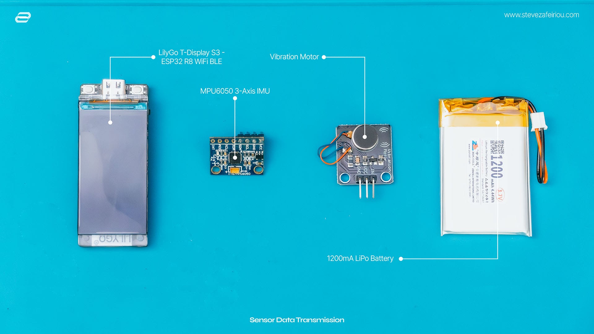
- LilyGo T-Display S3 or any other esp32 development board.
- MPU6050 Accelerometer Module
- Vibration Motor
- Jumper wires and breadboard or custom PCB
- Power supply (e.g., USB cable or LiPo battery)
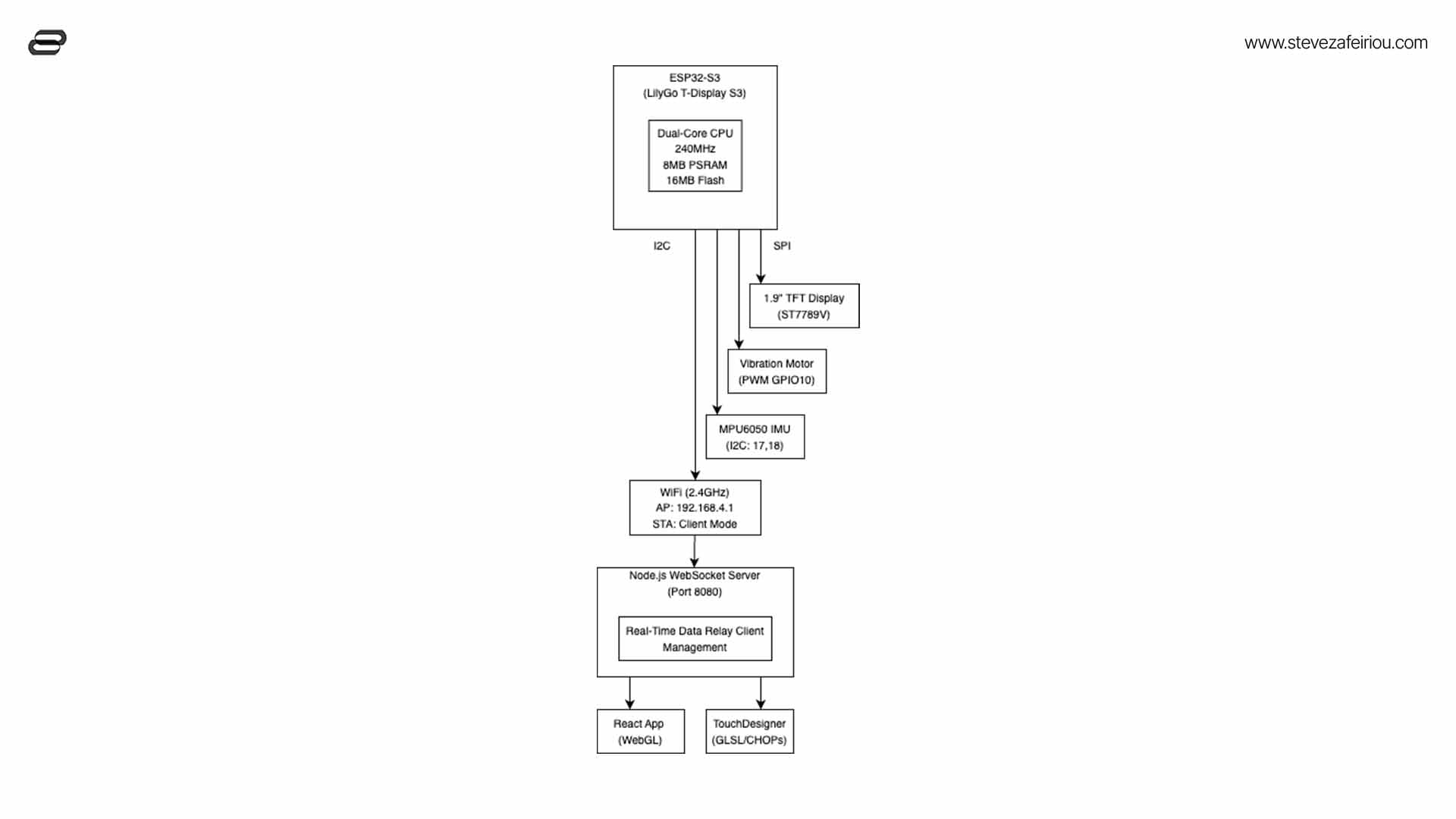
| LilyGo T-Display Pin | MPU6050 Pin | Vibration Motor Pin |
|---|---|---|
3V3 |
VCC |
Positive terminal |
GND |
GND |
Negative terminal |
GPIO18 |
SCL |
|
GPIO17 |
SDA |
|
GPIO10 |
Motor Positive Terminal |
Note: The TFT display is integrated into the LilyGo T-Display S3 board and requires no additional wiring or configuration.
-
Set Up the Arduino IDE:
-
Follow this guide to set up the LilyGo T-Display S3 in the Arduino IDE:
LilyGo T-Display S3 - Setup Guide -
Install the Required Libraries:
TFT_eSPI(pre-configured for the T-Display)WebSocketsClientPreferencesAdafruit_MPU6050
-
-
Upload the Firmware:
- Open the
SensorDataTD/SensorDataTD.inofile in Arduino IDE. - Select the LilyGo T-Display S3 board under
Tools -> Board. - Upload the firmware to the board.
- Open the
-
WiFi Configuration:
- On first boot, connect to the
SensorDataTDWiFi network. - Navigate to
192.168.4.1in your browser to configure WiFi and server IP.
- On first boot, connect to the
Read the ESP32 Firmware Documentation
-
Install Node.js:
- Download and install Node.js from https://nodejs.org/.
-
Set Up the Server:
- Navigate to the
server/directory:cd server - Install dependencies:
npm install
- Run the server:
node server.js
- The server will start on port
8080and display your local IP addresses. Use one of these addresses to configure the ESP32 WebSocket connection.
- Navigate to the
The React app provides a 3D visualization of the sensor data.
-
Navigate to the React App Directory:
cd react-app -
Install Dependencies:
npm install
-
Run the Development Server:
npm start
Open http://localhost:3000 to view the app in your browser. The app will display real-time sensor data and update the rotation of a 3D model.
Read the React App Documentation
-
Print the Case:
- Use the
.stlfiles in themodels/folder to print the enclosure. - Recommended settings:
- Material: PLA or PETG
- Layer Height: 0.2mm
- Infill: 20%-30%
- Use the
-
Assemble the Hardware:
- Place the LilyGo T-Display S3, MPU6050, and vibration motor into the case.
- Use screws or adhesive as needed to secure the components.
-
Start the ESP32:
- Power on the LilyGo T-Display S3. It will connect to WiFi and start transmitting sensor data to the WebSocket server.
-
Start the Server:
- Ensure the server is running and the LilyGo T-Display S3 is configured with the correct WebSocket server IP.
-
Monitor the Data:
- Open the React app to visualize real-time 3D data updates.
- Alternatively, connect a WebSocket client to the server (e.g.,
ws://<server_ip>:8080) to view the raw sensor data.
-
WiFi Issues:
- Check the SSID and password in the WiFi configuration portal.
- Ensure the target network is available and within range.
-
Server Not Receiving Data:
- Verify the LilyGo T-Display S3 is configured with the correct server IP.
- Check that the Node.js server is running and listening on port 8080.
-
React App Issues:
- Ensure the WebSocket URL in the
react-app/src/App.jsfile is correctly configured to match the server's IP address.
- Ensure the WebSocket URL in the
-
Accelerometer Data Issues:
- Ensure the MPU6050 is connected to the correct pins (
SCL -> GPIO18,SDA -> GPIO17). - Verify that the MPU6050 module is powered.
- Ensure the MPU6050 is connected to the correct pins (
-
Vibration Motor Not Working:
- Check the wiring for the motor (
Input -> GPIO10). - Verify that the vibration threshold is configured appropriately in the firmware.
- Check the wiring for the motor (
-
FOR ESP32:
- Add DEEP SLEEP mode to save power OR add a switch.
- Include OTA functionality, in order to program the device wirelessly.
-
FOR MODELS:
- Include specific positions and clips to attach the components + the LilyGo.
- Maybe include an ON-OFF switch.
This project is licensed under the MIT License. See the LICENSE file for details.
Contributions are welcome! Feel free to submit issues, feature requests, or pull requests.
For questions or support, please contact steve@saphirelabs.com.