Hey Ross, I am planning to do a through-hole clone of the Muskrat for my own rack and would like to ask some clarifying questions about the circuit:
Knob / Pin / Parameter mappings
Is my understanding below correct?
- Scratch == “Size” or “[??] Select” (schematic) == pot1 / fuckery (code) == A1/ADC1/PB2
- Chew == “Pitch" (schematic) == pot2 / pitch (code) == A2/ADC2/PB4
- Dig == “File” (schematic) == pot3 / select (code) == A3/ADC3/PB3
- Muskrat Switch / Input == “Reverse” or “Toggle in” (schematic) == trigState (code) == 1/MOSI/PB0
Pin mapping typo in the schematic?
If my understanding above is correct, then I believe the schematic has incorrect labels for the MCU pins:
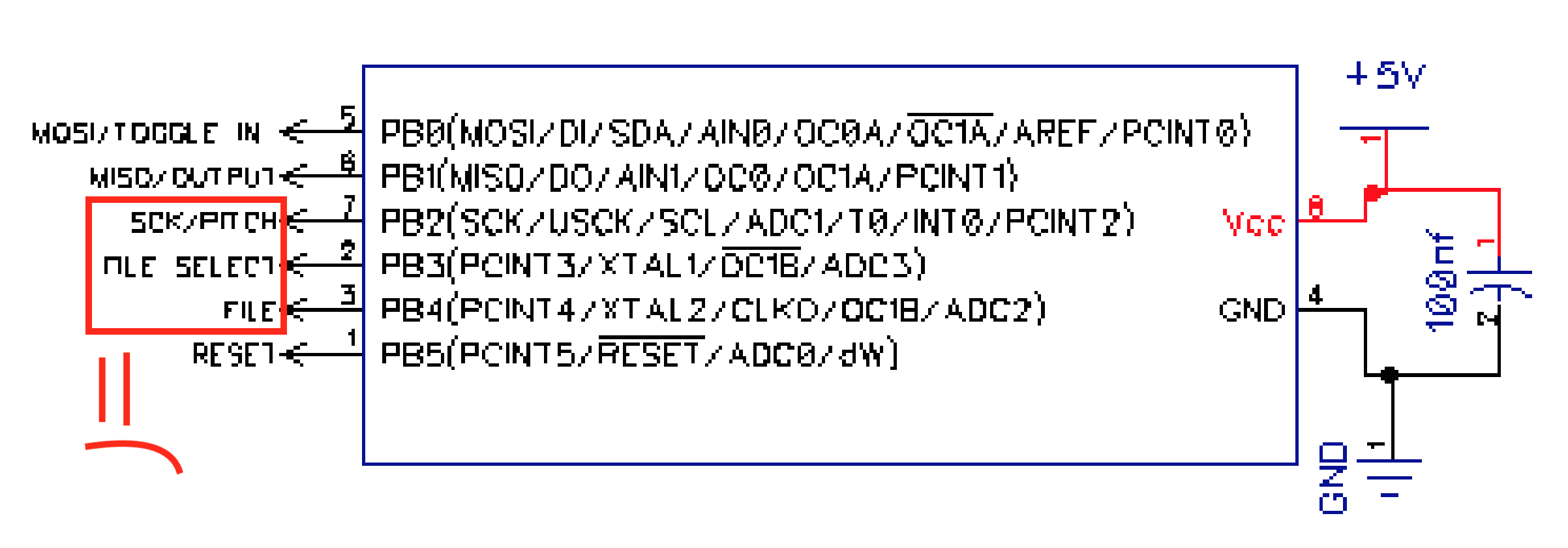
According to the code, I think the schematic should read:
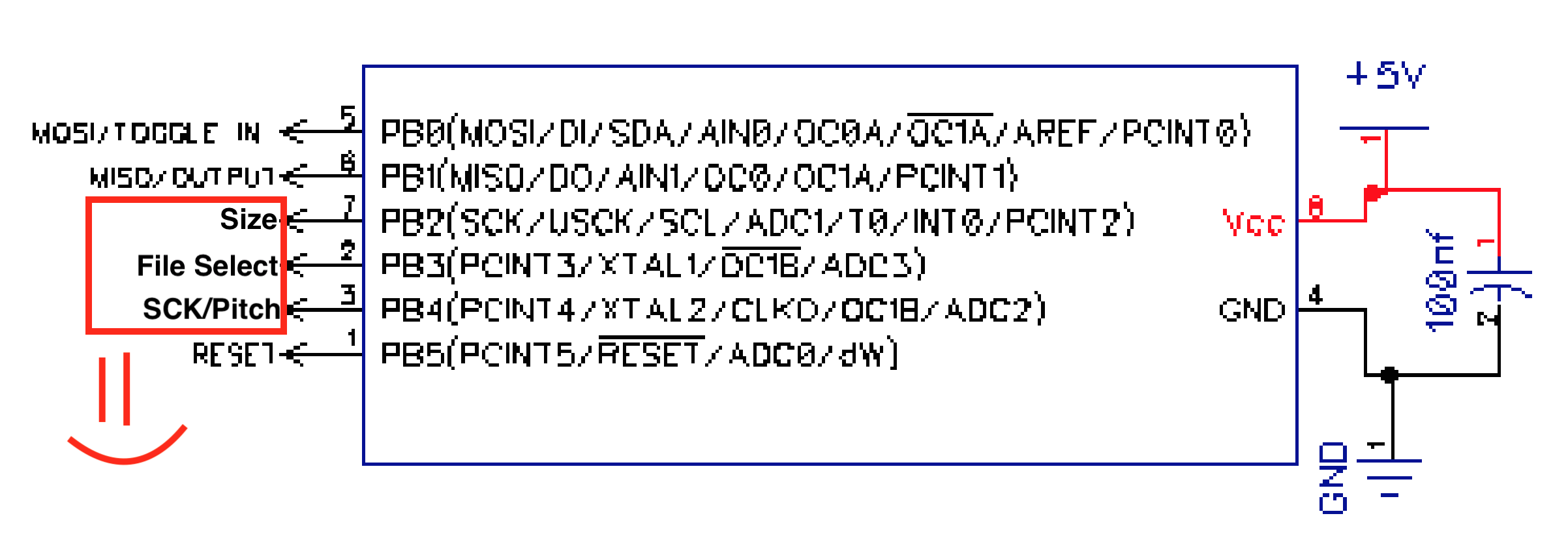
Is this correct?
What dis mean?
I don’t know what to make of this “/ MISO” on the unconnected pin of the Muskrat Switch:
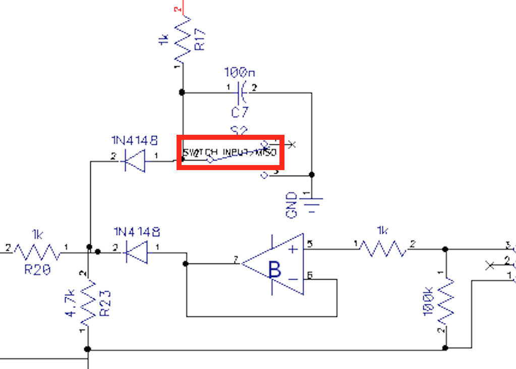
If anything, I’d expect it to say “/ MOSI” as this is where the toggle input goes. It would also make sense that it doesn’t actually mean anything and this pin has no connection.
And then what dis mean?
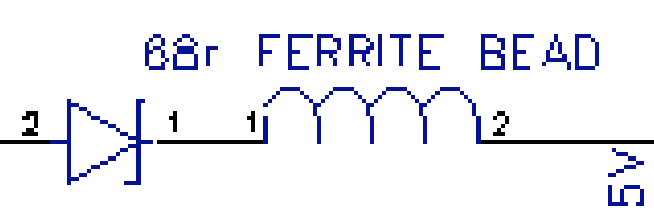
What does this “68r” mean by the ferrite beads? Does it mean a 68R resistor could replace the ferrite beads?
CV connections to the ATTiny
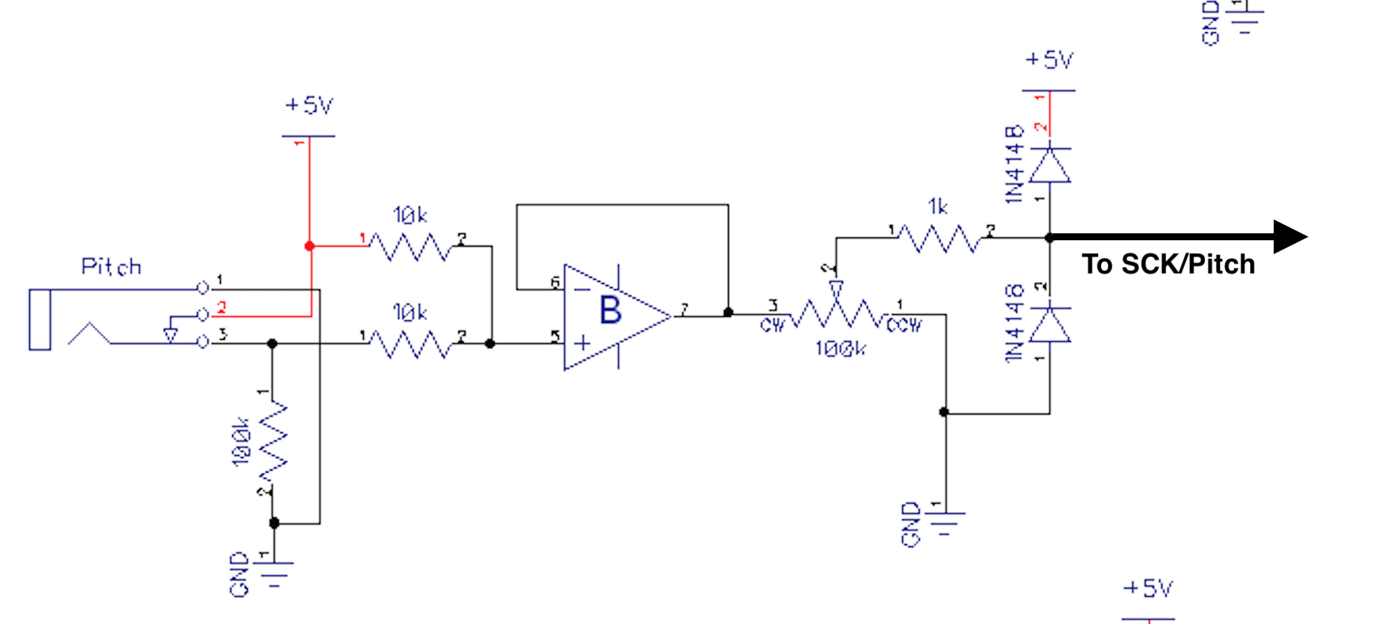
There’s nothing I can see in the schematic that explicitly denotes which parts of the circuit are connected to which pins of the ATTiny, but I think the idea is straightforward: There are 4 parameters and there’s an input circuit with clipping diodes for each one.
So does each CV input connect to a pin on the ATTiny like below?
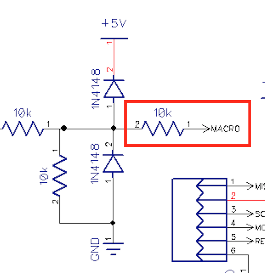
Should I add a 10k resistor between the clipped CV and the pin as you do in the Dialup circuit?
Components
Here’s what I’m assuming about the components based on what you told me for the GMO:
- All clipping diodes are labeled as 1N4148 in the schematic so they should be fine, although schottkeys might clip harder.
- Reverse protection diodes are 60v 1A B160-13-F schottkeys
- 5v reference is 78L05 or 7805
- All op amps are TL07x
- Transistors are 2N3904
Thanks!!
Sorry for the wall of text and thank you for your hard work! Keep it up :) good shit
Hey Ross, I am planning to do a through-hole clone of the Muskrat for my own rack and would like to ask some clarifying questions about the circuit:
Knob / Pin / Parameter mappings
Is my understanding below correct?
Pin mapping typo in the schematic?
If my understanding above is correct, then I believe the schematic has incorrect labels for the MCU pins:
According to the code, I think the schematic should read:
Is this correct?
What dis mean?
I don’t know what to make of this “/ MISO” on the unconnected pin of the Muskrat Switch:
If anything, I’d expect it to say “/ MOSI” as this is where the toggle input goes. It would also make sense that it doesn’t actually mean anything and this pin has no connection.
And then what dis mean?
What does this “68r” mean by the ferrite beads? Does it mean a 68R resistor could replace the ferrite beads?
CV connections to the ATTiny
There’s nothing I can see in the schematic that explicitly denotes which parts of the circuit are connected to which pins of the ATTiny, but I think the idea is straightforward: There are 4 parameters and there’s an input circuit with clipping diodes for each one.
So does each CV input connect to a pin on the ATTiny like below?
Should I add a 10k resistor between the clipped CV and the pin as you do in the Dialup circuit?
Components
Here’s what I’m assuming about the components based on what you told me for the GMO:
Thanks!!
Sorry for the wall of text and thank you for your hard work! Keep it up :) good shit