Home
Geometry Description Markup Language (GDML) is a specialised XML-based language for describing 3D geometry used by Monte Carlo simulation software such as GEANT4, ROOT, and OpenMC. See the GDML Manual for the full specification, and the GDML Solids reference for the complete list of supported solid types.
The GDML Workbench for FreeCAD lets you:
- Import GDML geometry files from GEANT4, ROOT, or OpenMC
- View and navigate complex volume hierarchies
- Edit solid parameters, materials, and placements interactively
- Create GDML geometry from scratch using native GDML solid types
- Export to GDML (single or multi-file), or to OpenMC XML
From the FreeCAD command bar select View → Workbench then select GDML.
When the GDML workbench is active it is recommended that the following toolbars are visible:
- Workbench
- Structure
- GDMLTools
- GDML Part Tools
The icon bar should look similar to:
![]()
To make a toolbar visible: View → Toolbars
GDML Solids are implemented as FreeCAD Python objects with the same properties as defined by the GDML specification. Selecting an object allows its properties to be changed in the FreeCAD Properties panel, with changes immediately reflected in the 3D view.
 A rectangular box defined by half-lengths x, y, z.
 A cone or cone section, defined by inner/outer radii at each end and a z half-length.
 An elliptical tube defined by semi-axes dx, dy and half-length dz.
 An ellipsoid defined by semi-axes ax, by, cz with optional z clipping planes.
 A full sphere or spherical shell/section, defined by inner/outer radii and angular ranges.
 A general trapezoid with independently specified face dimensions.
 A cylindrical tube or tube section, defined by inner/outer radii, z half-length and phi range.
Many more GDML solid types are supported on import. If you need a particular solid type available for creation in the GUI, please open an issue or contact the author.
Select two Parts (GDML Logical Volumes) in the tree view and click the appropriate Boolean icon (Union, Intersection, Subtraction).
- Scan GDML file — recommended for large GDML files (Alice.gdml, LHCb.gdml, etc.)
On opening or importing a GDML file, a dialog offers two modes:
- Import — full import of all geometry (suitable for small to medium files)
- Scan Vol — loads volume names only; individual volumes can be expanded on demand
The first icon on the GDML toolbar cycles the display mode of a selected volume (and all its children) through: Solid → Wireframe → Hidden → Solid.
Select a volume either from the tree view or by Ctrl+clicking a face in the 3D view, then click the cycle icon.
Select any GDML solid in the tree view to edit its parameters in the Properties panel. Changes are reflected immediately in the 3D view. Hit Enter after typing a value (do not just click away) to confirm the change.
Placement (position and rotation) of a solid is controlled via its parent Part's Placement property.
Anatomy of a GDML Workbench Document
When a new file is created from the GDML workbench, a Geant4 materials group is loaded from Geant4Materials.xml, providing all materials that GEANT4 defines implicitly. On export, these are omitted by default (since GEANT4 provides them automatically). To include them — for example when targeting ROOT — enable Export Geant4 Materials in the workbench preferences:

User materials can be added by importing an XML file (File → Import) formatted as:
<xml>
    <materials>
        <!-- Isotopes, Elements, and Material definitions -->
    </materials>
</xml>
To extract materials from an existing GDML file: import it, select the Materials Group, then File → Export with a .xml extension. The exported file can then be imported into any other document.
The Add Material form (accessible from the GDML menu or toolbar icon) supports three modes:
-
By chemical formula — e.g.
H2O,(CH2)3— elements and their counts are parsed automatically -
By mixture — e.g.
0.5 G4_DNA_A + 0.5 G4_DNA_B— mix existing materials by fraction -
By isotopic composition — e.g.
0.20 235U + 0.80 238U— define an element from its isotopes
Material density units: mass in kg, g, or mg; volume in mm3, cm3, or m3.
See the Home page section on materials in Anatomy of a GDML Workbench Document for screenshots of the form.
In addition to native GDML solids, the workbench supports exporting a range of FreeCAD Part objects. For shapes that cannot be represented as GDML primitives, the recommended approach is to tessellate them using the GDML workbench tools, or use software such as McCad to decompose BREP shapes into GDML primitives.
Shapes created in the Sketch Workbench and extruded via Part → Extrude can be exported to GDML as a series of boolean operations on intrinsic GDML solids. The extrusion must be placed under a Part within the WorldVol tree.
Performance note: GEANT4 simulations with extruded sketches exported as booleans run 2–5× faster than equivalent tessellations. See timing tests.
Smoothness: The discretisation of curves (BSplines, arcs) is controlled by the Deviation property in the object's View panel. Lower values give smoother curves; the default is 0.5%.
Note: Re-importing an exported GDML file will show the expanded boolean structure, which differs from the original FreeCAD extrusion object.
Shapes created in the Sketch Workbench and revolved via Part → Revolve can be exported as a series of booleans (tubes, polycones). Revolves around the principal x, y, z axes are fully supported. The revolution must be placed under a Part within the WorldVol tree.
Note: Re-importing an exported GDML file will show the expanded boolean structure.
Orthogonal, polar, path, and point arrays (created via Draft Array or the GDML Array command) are exported as a single GDML multiUnion solid. The array must be under a Part in the WorldVol tree. Arrays of arrays are supported. Assign material to the Array object itself for best results.
Examples of Arrays | Examples of Arrays of Parts
Mirrors of GDML-exportable objects (including extrusions, revolutions, arrays) can be exported. Both the original and its mirror are placed in a GDML <assembly> and share the original material.
GDML solids can be scaled using the GDML Scale command, which adds a scale property to the selected solid. Draft-scaled objects (clones) are also supported; the clone must be in the WorldVol tree while the original remains outside it.
The following Part Workbench objects are tessellated automatically on export — no explicit tessellation step is required:
- Lofts
- Sweeps
- Chamfers
- Fillets
- Any
Part::FeaturePythonobject (e.g. from the Fasteners, Gears, or Pyramids & Polyhedra workbenches)
Examples of Chamfers and Fillets | Loft | Sweep | Nuts and Bolts | Polyhedra | Gear
Use the GDML tessellation tools to convert FreeCAD shapes to GDML <tessellated> solids:
- Tessellate — uses FreeCAD's built-in mesher
- Tessellate via Gmsh — opens a panel with mesh type and quality controls; supports re-meshing
- Gmsh Min Tessellate — uses Gmsh's recombination algorithm to reduce facet count (e.g. a cube becomes 6 quads rather than 12 triangles)
- FC Mesh → GDML Tessellated — converts any FreeCAD mesh (STL, PLY, etc.) to a GDML tessellated solid
- GDML Tessellated → FC Mesh — converts back for use with FreeCAD mesh tools
See Step2Tessellate and Tessellating Part Design Objects for full workflows.
Select the root Part (GDML World Volume) then File → Export.
| File type | Result |
|---|---|
gdml (lowercase) |
Single self-contained GDML file |
GDML (uppercase) |
Multi-file: a root .gdml plus separate setup.xml, constants.xml, defines.xml, materials.xml, solids.xml, structure.xml
|
Note: ROOT does not support multi-file GDML (it requires DOCTYPE entities). Use the single-file export for ROOT, or combine a multi-file export using the combineGDML.py utility in the Utils/ directory.
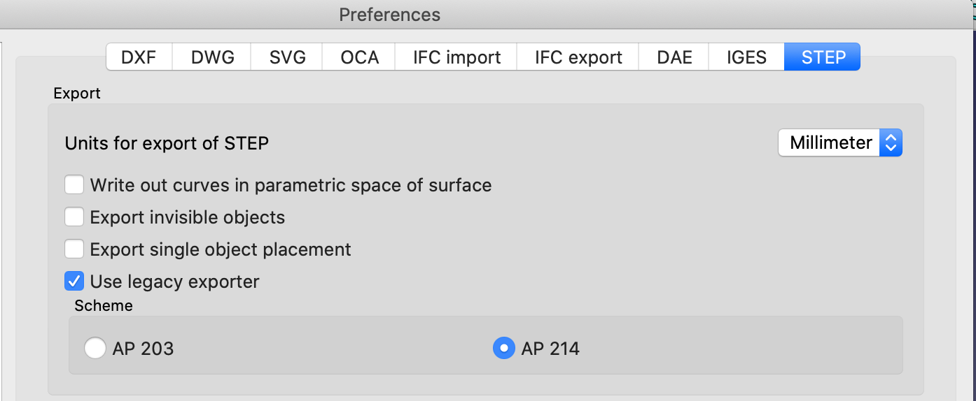
When exporting STEP files that include GDML objects, set the FreeCAD STEP export preference to use the legacy exporter:
The workbench can export a FreeCAD GDML document to the geometry and materials XML files used by OpenMC. This feature is alpha — test all exported geometry carefully before use in simulation. See Export to OpenMC for full details.
The workbench supports GDML optical surface definitions (OpticalSurface, SkinSurface, BorderSurface). See Optical Support.
To verify that an exported GDML file matches the FreeCAD geometry, use the centre-of-mass / moment-of-inertia comparison tools:
- FreeCAD macro: calcCenterOfMass.py
- GEANT4 application:
load_gdml_colorwith the-printCMflag — see Validation Tools
If the total volume, centre of mass, and moments of inertia match between the two, the geometries are almost certainly identical.
Use the Compound icon to prepare a GDML geometry for FEM analysis. This creates a Compound object and an FEM Analysis object under the selected volume, with all GDML materials added automatically. Switch to the FEM Workbench to proceed with meshing and solver setup.
Standalone command-line utilities are maintained in GDML_Command_Line_Utils and in the Utils/ directory of the main repository. These include:
-
gdml2step.py— convert a GDML file to STEP format -
combineGDML.py— merge a multi-file GDML export into a single file -
listVols.py,listSolids.py— inspect GDML file contents
For installation instructions see the README.